| Hack a Day ( @ 2014-01-03 18:00:00 |
|
|
|
|
|
|
|
|
|
|
|
|
|
|

In case you weren’t aware, having a 3D printer is nothing like owning a real-life Star Trek replicator. For one, replicators are usually found on Federation starships and not hype trains. Secondly, the details of how replicated objects are designed in the 24th century is an issue completely left unexplored by TNG, and DS9, and only a minor plot point in a few Voyager episodes. Of the most likely possibilities, though, it appears replicated objects are either initially created by ‘scanning’ them with a teleporter, or commanding the ship’s computer to conjure something out of the hologrid.
No, with your own 3D printer, if you want a unique object you actually have to design it yourself. Without a holodeck. Using your hands to move a mouse and keyboard. Savages.
This series of ‘Making a Thing’ tutorials aims to fix that. With this post, we’re taking a look at Blender, an amazing 3D modeling and animation package.
Because we still haven’t figured out the best way to combine multiple blog posts together as a single resource − we’re working on that, though − here’s the links to the previous “Making a Thing” posts:
This list is sure to grow thanks to your suggestions on what 3D modeling software to feature, but for now let’s make a thing in Blender.
Our Thing
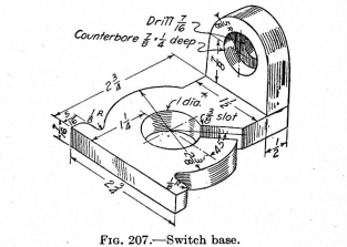
To the right is the part we’ll be designing in Blender. Just like the OpenSCAD and AutoCAD tutorials, we’re using the same object, a weird switch base thing taken from a 90-year-old book on drafting. You can click to embiggen that.
A Word About Blender
Blender is designed as a 3D animation suite. You know the old mid-90s Pixar short films? You can make those with Blender easily. Using Blender to design a small object to send to a 3D printer is like using a bulldozer to build a sand castle. You can do it, but it’s overkill.
Ideally, Blender should be used for objects that aren’t mechanical in nature. If you’re designing a gearbox for an RC car, don’t use Blender. If you’re making a replica of the Antikythera mechanism, don’t use Blender. If, however, you’re designing something more sculptural – a Pietà, for instance – Blender is a great tool.
Despite Blender being complete overkill for this simple part, and the fact Blender isn’t well suited for designing mechanical parts anyway, a lot of people asked for a Blender tutorial. Who am I to argue with the commentors on Hackaday?
Starting Up
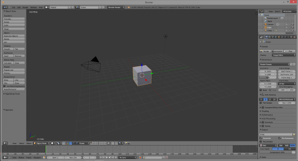
Installing Blender is left as an exercise to the reader. Do that here. When you first start Blender you’ll see the following screen that includes a cube, a camera (the pyramid-looking thing), and lamp. This is the default starting screen and we don’t need any of these objects. On your right hand toolbar, go to your Scene tab (at the top of the toolbar), right-click the cube, camera, and lamp, and delete them.
Meshes
Now that we have a blank canvas, we can start designing our part. Since this part of this tutorial is already halfway done, we’re only going to design the ‘washer’ part of our thing – the circle with a 3/8″ slot.
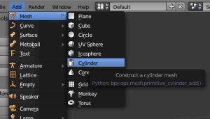
Instead of editing solids like OpenSCAD and AutoCAD, Blender does things entirely differently. It uses meshes, or collections of vertices (points in 3D space), edges (lines between two vertices), and faces (polygons made of edges) to define an object. We can start building our thing by making a cylinder mesh. From the top menu bar, select Add -> Mesh -> Cylinder and left click. A cylinder will appear at coordinates 0,0,0 in your scene.
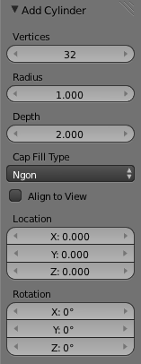
After you’ve done this, you’ll see an ‘Add Cylinder’ window on your left hand toolbar. This window allows you to edit the number of vertices, the radius, and the depth of the cylinder. Now is a good of a time as any to start editing our part, so make the radius of the cylinder 1.1875 (one half of the 2 3/8″ diameter of our part), and the depth 0.4375.
By the way, yes, I am regretting using a part from a 100-year-old drafting textbook right about now.
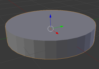
Here’s what we end up with:
That’s making a very primitive object in Blender. To make anything useful, though, we need to go into edit mode.
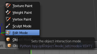
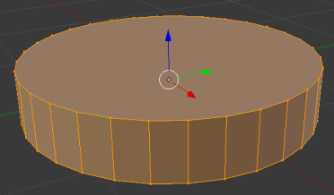
At the bottom of your Blender window, you’ll find a menu that will change how you can interact with Blender. Right now we’re in Object mode, which allows for the creation of meshes, surfaces, cameras, and lamps. To edit our object we need to be in…. Edit mode. Click on the little pull-down menu and change over. Doing this allows us to edit all the vertices, edges, and faces of our object. Here’s the cylinder we just created with all these selected:
Hit the ‘A’ key on your keyboard to deselect everything. Now the cylinder is gray.
Now we need to put a hole in this part of our thing. If we were modeling with solids, we would simply create another cylinder, smaller than the one we have now, and subtract it from our current model. We’re not working with solids, though; we need to create the faces of our objects without Boolean operations.
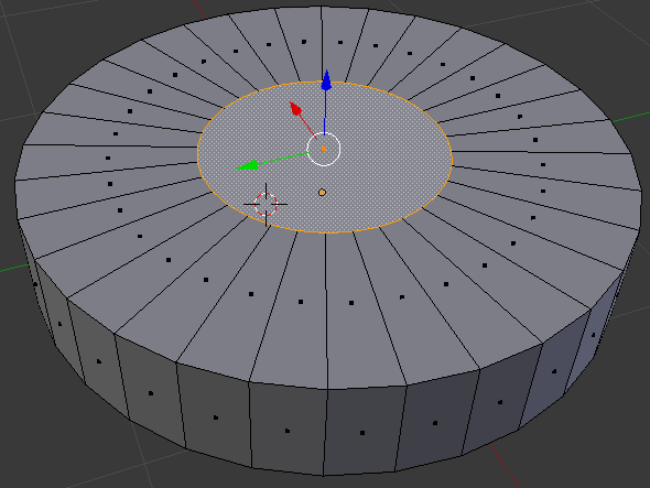
To create the hole in this part of our thing, select the top face of the cylinder and with the ALT+F keyboard combo, select inset faces with the tool tip pop up thingy. Insetting a face allows us to create a new top and bottom for this cylinder that will correspond to the exact sized hole we need.
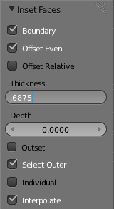
When you enable the Inset Faces command, the size of the hole you’re creating is dependant on how far you move your mouse; not great for something we’re creating from precise measurements. On the left hand toolbar, though, you can enter the thickness we want.
Here’s how the math goes, if you’re wondering. The ‘cylinder’ of our part is 2 3/8″ in diameter, and we want a 1″ diameter hole in the middle. Subtract 1 inch from 2.375 and you get 1.375. Since the thickness of this face is in reality a radius, divide 1.375 by two and you’ll get the number we want. I truly hate decimal inches.
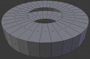
After deleting the top part of our hole, flip the part over in Blender and do the same thing to the other circular face of our part. You’ll end up with something like this:
Now all we need to do is join up the top and bottom faces.
 On the toolbar where you selected Edit Mode, you’ll see a set of three buttons. One is a cube with a vertex highlighted, one is a cube with an edge selected, and the other is a cube with a face selected. Any ideas what these buttons do?
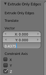
Instead of individually selecting each of these edges on the inside of our part and creating 36 individual faces, we’re going to do something much simpler. Holding down the ALT key, select one of the inside edges with the right mouse button. This enables edge loop selection. Now, on the mesh tools toolbar (left side), hit Extrude and press the ‘Z’ key on your keyboard to lock your mouse input to one axis of movement.
Again on the right toolbar, you’ll see a trio of boxes labeled ‘Vector’. This is how far Blender will extrude our…. extrusion in the X, Y, and Z axis. We want to extrude this edge 7/16″ (or 0.4375 decimal inches in the negative Z direction. That’s easy enough.
Here’s what we end up with when that’s done. Yes, it took me one thousand words to describe how to create a washer in Blender.
So what did you just learn?
As far as the creation of our ‘thing’ in Blender, we didn’t get very far. There’s still flanges and holes and round overs to do, but this is only part one of this Blender tutorial. Hopefully this served as a good introduction to Blender’s meshes and editing those mesh’s faces and edges.
See you here again next week!
Filed under: 3d Printer hacks, Hackaday Columns, how-to
