[Most Recent Entries] [Calendar View] [Friends]
Below are the 20 most recent journal entries recorded in
Hack a Day's LiveJournal:
| Sunday, January 5th, 2014 | |
| 3:00 pm | Retro Chaser Sign Lights Up Your Life
[Gnsart] builds props often used in the film industry. He’s created an amazing retro Vegas style light chaser sign. The sign was started as a job a few years ago. While [Gnsart] could handle the physical assembly, the cost of a mechanical light chaser pushed the project over budget. The sign project was cancelled back then, but he never forgot it. Fast forward to a few weeks ago. [Gnsart] happened upon the Arduino community. He realized that with an Arduino Uno and a commonly available relay board, he could finally build the sign. He started with some leftover cedar fence pickets. The pickets were glued up and then cut into an arrow shape. The holes for the lights were then laid out and drilled with a paddle bit. [Gnsart] wanted the wood to look a bit aged, so he created an ebonizing stain. 0000 steel wool, submerged and allowed to rust in vinegar for a few days, created a liquid which was perfect for the task. The solution is brushed on and removed just like stain, resulting in an aged wood. We’ve seen this technique used before with tea, stain, and other materials to achieve the desired effect. [Gnsart] then built his edging. 22 gauge steel sheet metal was bent to fit the outline in a bending brake. The steel sheet was stapled to the wood, then spot welded to create one continuous piece. Finally, the light sockets were installed and wired up to the Arduino. [Gnsart] first experimented with mechanical relays, and while we love the sound, we’re not sure how long they’d last. He wisely decided to go with solid state relays for the final implementation. The result speaks for itself. LEDs are great – but there is just something about the warm glow of low-wattage incandescent lights.
Filed under: Arduino Hacks, misc hacks  |
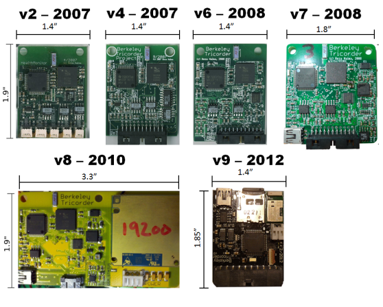
| 12:00 pm | The Berkeley Tricorder is now Open Source!
[Reza Bauna] has just released the designs for his Berkeley Tricorder for the public to use. He’s been designing it since 2007 as his thesis work for his PhD, and since he’s done now (Congrats!), he decided to let it grow by making it open source! We covered it almost 7 years ago now when it was in its first prototype form, and it has come a long way since then. The latest version features an electromyogram (EMG), an electrocardiograph (ECG), a bioimpedance spectrometer, a pulse oximeter, an accelerometer, and all the data is recorded to a micro SD card or sent via bluetooth to a tablet or smart phone for data visualization. He’s released it in hopes that other researchers can utilize the hardware in their own research, hopefully springing up a community of people interested in non-invasive health monitoring. With any luck, the development of the Berkeley Tricorder will continue, and maybe some day, can truly live up to its name! Unfortunately there’s no new video showing off the latest iteration, but we’ve attached the original video after the break, which gives a good narrative on the device by [Reza] himself.
Filed under: Medical hacks  |
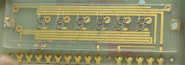
| 9:00 am | Testing The Limits Of Home PCB Etching
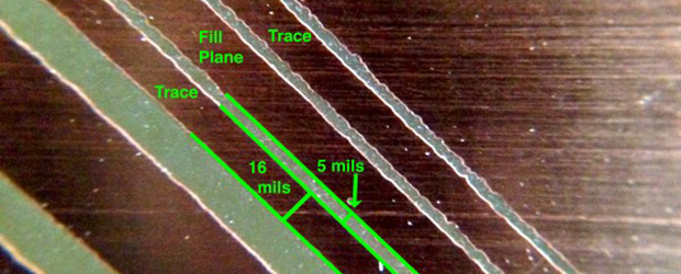
[Quinn Dunki]‘s Veronica, a homebrew computer based on the 6502 CPU, is coming along quite nicely. She’s just finished the input board that gives Veronica inputs for a keyboard and two old Nintendo gamepads. [Quinn] is building this computer all by her lonesome, including etching all the PCBs. She’s gotten very, very good at etching her own boards, but this input board did inspire a few facepalming moments. In an earlier post, [Quinn] went over her PCB etching capabilities. As demonstrated by the pic above, she’s able to print 16 mil traces with 5 mil separation. This is just about as good as you can get with homebrew PCBs, but it’s not without its problems. [Quinn] is using a photographic process for her boards where two copies of a mask is printed on an acetate sheet, doubled up, and laid down on a pre-sensitized copper board. The requirement for two layers of toner was found by experience – with only one layer of toner blocking UV light, [Quinn] got some terrible pitting on her traces and ground planes. Two photographic masks means the masks must be precisely aligned. This example shows what happens when the acetate sheets are ever so slightly misaligned. With a 5 mil gap between traces, [Quinn] needs to align the masks to within ±2.5 mils; difficult to do by eye, and very hard once you factor in flexing and clamping them down to the copper board. Even when this process goes perfectly, [Quinn] is pushing the limits of a laser printer. When printing at 600 dpi, the pixels of the print are about 1.5 mils. While GIMP, printer drivers, and the printer itself have some fancy software to help with the interpolation, [Quinn] is still seeing ‘bumps’ on the edges of perfectly aligned parts. This is one of those things that really makes you step back and realize how amazing fabbing PCBs at home actually is. With most of the hardware for Veronica out of the way, it’s just about time for [Quinn] to start programming her baby. We’re not expecting a full-blown operating system and compiler, but those NES gamepads are probably crying out for some use. Filed under: hardware  |
| 6:00 am | International Obfuscated C Code Contest Winners Posted
The International Obfuscated C Contest – the contest to create the most useful, useless, or unique program in absolutely unreadable C code – has just posted the winners of the 2013 contest. Of the entries of note, a few really stand out. The pic at the top of this post, for instance, comes courtesy of this submission. It’s an iterative ray tracer stuck inside an infinite loop that, when left running overnight, is able to produce amazing renders. An IOCCC contest wouldn’t be complete without some ASCII art C code, and this entry fits the bill. It’s a Tetris painting tool that creates images made out of tetronomoes. Each image is built up one line at a time from the bottom up, using Tetris’ lack of physics to create a picture out of un-cleared lines. One of the most impressive entries for this (last?) year’s contest is a tiny 8086 PC emulator/virtual machine written in only 4043 bytes of code. It’s a fully functional 80s-era PC emulator that can run vintage copies of AutoCAD, Windows, Lotus 1-2-3, and SimCity. All the submissions are awesome, but like any IOCCC contest, there aren’t actually any winners. Or they’re all winners. The Obfuscated rules aren’t very clear in that regard. Filed under: Software Development  |
| 3:01 am | Ninja-Drillpress-Skills Produced this Glow Plug Extruder
Still looking to make your own 3D printer? Don’t have many tools or a big budget? Well, [Adam Kemp] has just the hack for you — a DIY extruder that can be made with only a drill press and a few hand tools. First, a little background. [Adam] loves the nitty gritty side of 3D printing, so he’s managed to build his own printer almost completely out of recycled parts from printers, scanners, etc. Unfortunately, there’s not much of an option when it comes to the extruder. Almost all designs online feature 3D printed parts. Not wanting to admit defeat, he came up with this clever glow plug extruder design. As you can imagine, it requires a lot of drilling, and it would be a heck of a lot easier on a mill — but that’s not the point here. He even goes into detail on how to hob the extruder feed wheel using nothing but a tap, a drill press, some skateboard bearings, and a few washers and nuts. The entire guide is great, so if you want to feel like MacGyver for a few hours and you need a good extruder, try it out! To see the extruder in action, stick around after the break.
[Via Reddit] Filed under: 3d Printer hacks  |
| 12:01 am | Build a Simple Audio Amp
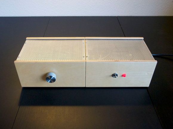
[Ynze] has built an audio amplifier that looks and sounds great. His amplifier uses a National Instruments (now TI) LM3886 Overture series 68 Watt power amp. The LM3886 places [Ynze's] amp squarely in the “Gainclone” catagory. Gainclone or Chipamp are terms long used by the DIY community to describe audio amps based upon highly integrated semiconductor amplifiers. The Gainclone name stems from the original Gaincard audio amplifier sold by 47 labs. The Gaincard used less than $100 USD of parts when it was introduced in 1999. It sounded good enough to command a $3300 USD price tag on the audiophile market. The low parts count and simple construction spawned the audio DIY community to build their own versions of the Gaincard. Hundreds of variants exist now, and wading through the different versions can be a bit of a daunting task. [Ynze] found a basic design that works, and built from there. One of the interesting things about [Ynze's] amp, as well as many of the Gainclones, is the fact that they use no circuit board. All wiring is done point to point. resistors are soldered directly to the pins of the amplifier chip. This can be some tricky soldering for beginners, but several PCB kits are available. [Ynze] built his amp in two cases. One case holds the power supply, and the other contains the amplifier itself. [Ynze] is using a large toroid transformer to drop his local 230V mains down to +25V and -25V. The amplifier circuit itself is simple – a few discrete components surround the LM3886 and it’s heat sink. [Ynze] also did some very nice carpentry work on his wood chassis. The resulting amp looks like it’s right out of the 1960′s – but hides 1990′s electronics inside.
Filed under: digital audio hacks  |
| Saturday, January 4th, 2014 | |
| 9:00 pm | Interfacing with the HTC Desire Display and its Touch Panel
Part of [Linas]‘ submission to last year’s Cypress Smarter Life Challenge involved using the HTC Desire display and its touch screen. This particular phone includes a full-color active-matrix OLED (AMOLED) display that has a 3.7″ diagonal and a 480×800 resolution, resulting in a 252ppi pixel density. Using a MSO2024B oscilloscope, [Linas] originally started his adventure with the touchscreen by sniffing the I2C signals. As some math was required to extract the data, he later found the HTC Desire source code and included it on his STM32F429 (so much for reverse engineering!). After spending many hours searching for the AMOLED display and controller datasheets, [Linas] resorted to pay a company to get the resources he needed. He produced a custom-made PCB to provide the display with the required voltages, as well as offering a 0.1″ connector to interface with it. A RGB565 interface is used to communicate with the screen so only 65k out of the 16 million colors are used. You may download all the program files and datasheets in [Linas] write-up. Filed under: contests, hardware  |
| 6:00 pm | A Guitar From an Old Tin Box
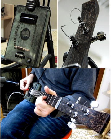
[Atdiy and Whisker], collectively known as [The Tymkrs] have been busy honing their luthier skills. They’ve created a 10 part YouTube series about the construction of their new cigar box guitar. Instead of a cigar box though, they’ve substituted a 1920’s tin cigarette box. The Omar Cigarette company gave “Project Omar” it’s name. Like [Tymkrs] previous guitar, Omar is a three string affair. The neck was cut from Black Palm, which really shined when polished with a mixture of orange oil and beeswax. They also threw in a couple of new tricks on this build. Omar is an electric guitar, with a pickup custom wound by [Bob Harrison]. Omar also has frets, which creates a whole new set of complications. Frets are generally installed by cutting slits in the guitar neck with a fret saw. Rather than buy a new tool, [Tymkrs] created a simple jig for their mini table saw. The jig held the guitar neck perpendicular with the saw blade. This made quick work of the many fret slits to be cut. Installed frets must also be dressed and leveled, which is a time-consuming process. The tin cigarette box also created a new set of problems. The thin tin proved to be a bit on the weak side when the strings were tightened down. A bit too much pressure on the box while playing would cause notes to bend, much like the tremolo or whammy bar on a standard electric guitar. [Tymkrs] were able to counteract this by adding bracing inside, and a couple of black palm braces to the back of the box. Hum was also a problem. When [Tymkrs] first plugged in, they found they had more 60Hz mains hum than signal from their strings. Omar uses a classic single coil guitar pickup. Single coils will pick up noise from any magnetic field, including the field created by the studio electrical system. A humbucking pickup uses two coils to counteract this effect. Humbuckers also have a slightly different tone than single coils. [Tymkrs] wanted to stick with their single coil tone, so they counteracted the hum by raising the pickup closer to the strings. Higher pickups receive more signal from the strings, so this is basically a free signal to noise ratio improvement. They also grounded the entire tin box, along with Omar’s metal tail stock. The final build sounds great, as evidenced by the jam session toward the end of Video 10.
Filed under: musical hacks, news  |
| 3:00 pm | [Fran]‘s LEDs, Nixies, and VFDs.
With a love of blinky and glowey things, [Fran] has collected a lot of electronic display devices over the years. Now she’s doing a few teardowns and tutorials on some of her (and our) favorite parts: LEDs and VFD and Nixie tubes Perhaps it’s unsurprising that someone with hardware from a Saturn V flight computer also has a whole lot of vintage components, but we’re just surprised at how complete [Fran]‘s collection is. She has one of the very first commercial LEDs ever made. It’s a very tiny red LED made by Monsanto (yes, that company) packaged in a very odd lead-and-cup package. Also in her LED collection is a strange Western Electric part that’s green, but not the green you expect from an LED. This LED is more of an emerald color – not this color, but more like the green you get with a CMYK process. It would be really cool to see one of these put in a package with red, green, and blue LED, and could have some interesting applications considering the color space of an RGB LED. Apart from her LEDs, [Fran] also has a huge collection of VFD and Nixie tubes. Despite the beliefs of eBay sellers, these two technologies are not the same: VFDs are true vacuum tubes with a phosphorescent coating and work something like a CRT turned inside out. Nixies, on the other hand, are filled with a gas (usually neon) that turns to plasma when current flows through one of the digits. [Fran] has a ton of VFDs and Nixies – mostly military surplus – and sent a few over to [Dave Jones] for him to fool around with. It’s all very cool stuff and a great lead-in to what we hear [Fran] will be looking at next: electroluminescent displays found in the Apollo Guidance Computer. Videos below.
Filed under: classic hacks, led hacks  |
| 12:01 pm | Recliner Sofa Given the Power of the Pi
If you go to buy a sofa these days you’ll not only be greeted with the option of one or more reclining positions, but a fully modern unit comes with motorized reclining. That simply wasn’t convenient enough for [Nicki] and [Kevin] who wanted to control the feature from a smartphone rather than a physical interface (buttons) on the side of the furniture. What resulted is the PiSofa, a Raspberry Pi connected to the furniture’s electronics with the help of a relay board. This is most certainly a hack, but no doubt one with a lot of finesse. Check out that white PCB. That’s right, it’s a factory spun board to keep things nice and neat. They went with one of our favorite tricks by housing everything inside of a food storage container. After some Ruby coding the Pi now has complete control of the sofa. We’re not overstating this. It literally is the only way to control it because the original buttons no longer work. But that’s okay, turns out not only does it work with their smartphones, but with a [Kevin's] Pebble watch as well. We can’t think of any past hacks that specifically targeted the couch. But here’s a hammock that you can drive down the street. Filed under: home hacks, Raspberry Pi  |
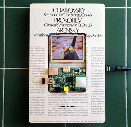
| 9:01 am | Building a Raspberry PI Digital Photo Frame
Digital photo frames aren’t very interesting on their own these days, but building one with a Raspberry Pi and strapping it with a bunch of useful features just might motivate you to check out this tutorial on building a ‘living’ digital photo frame. This is [Samuel’s] first project with the Raspberry Pi, so he decided to build a digital photo frame that has the ability to download random pictures from his Flicker account and display them in a slideshow format. With all that extra IO on the Raspi, it was easy to incorporate a status LED and PIR sensor. When motion is detected by the PIR sensor, the photo frame is enabled; after 60 seconds of no movement, the photo frame is disabled by turning off the monitor port. We love finding detailed write-ups like this because there is so much useful information in here like using the Flicker API, GPIO control, image handling, how to configure scripts to run on boot-up, and even some great troubleshooting code. If you’d rather ditch the Raspi altogether and take things down a few levels, check out this PIC based 100% DIY digital picture frame. Filed under: Raspberry Pi  |
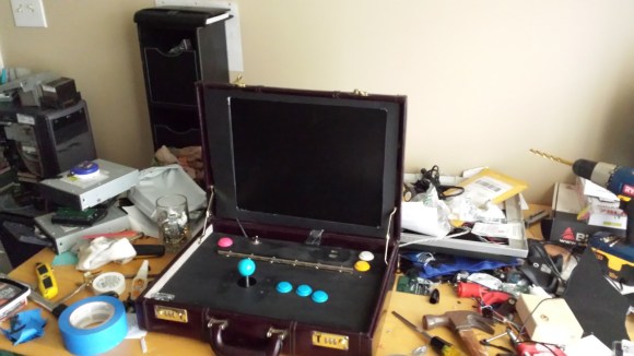
| 6:01 am | Arcade Briefcase (the Briefcade)
[Travis Reynolds] is part of an arcade club at work — the only problem? He’s the only one with an arcade machine, so they always end up at his place. So he decided to make his own portable, arcade briefcase to take to the office. It all started with a quick trip to Goodwill where he found a beautiful maroon briefcase from the 80′s, for only $5! He then took apart a spare LCD monitor he had sitting around, and it worked incredibly well in his favor. He was able to reuse the LCD’s internal mounting brackets to secure it to the briefcase, and the video cables were just long enough to reach the Raspberry Pi. The next problem he faced was the joystick height. He picked a Sanwa style joystick which is fairly small, but even that was too tall for the briefcase. So unfortunately, he needs to remove the ball of the joystick before closing the case. After testing out the proposed button layout, he cut a plywood mounting plate to hold everything in place. A bit of black spray paint later plus a power connector through the side of the case, and it’s complete! He’s running Shea Silverman’s PiMame, which has an easy to use menu, quick setup, and great support. It’s an awesome project, and very well documented in case you’re itching to do something similar — I know we are! Of course, if you have the space, a coffee table arcade machine is pretty sweet too… [Thanks Brendan!] Filed under: Raspberry Pi  |
| 3:00 am | Key Cutting with a CNC Mill
Keys cost like what, $2 to copy at a locksmith? But where’s the fun in that? Here’s an easy way to cut your own keys using a CNC mill! [Bolsterman] now “works” for a real estate company that rents out various properties. Whenever someone moves out, the locks need to be changed ASAP. They use Schlage locks, which can be re-keyed to any pin combination. New keys are typically cut with a punch or a key cutting machine — he actually had one years ago, but got rid of it. Not wanting to buy a new one for his new job at the real estate company, he decided to see how hard it would be to turn his small desktop CNC into his own personal key cutting machine. All it took for [Bolsterman] to turn his mill into a key cutting machine was a 3/8th 90° countersink bit with the end ground to a flat approximately 0.055″ across (0.035″ is the width of a factory key, but a bit of leeway makes it easier to make the key). Then you simply zero the mill off of the shoulder of the key, and using the handy Schlage pin chart (included in the original link), cut the grooves! To automate all of this, [Torrie Fischer] created a python script for generating the GCode for keys based on [Bolsterman's] technique — it’s hosted over at Noisebridge’s Wiki – check it out! But if all that seems like too much effort, you could just print a new key instead… Filed under: lockpicking hacks, security hacks  |
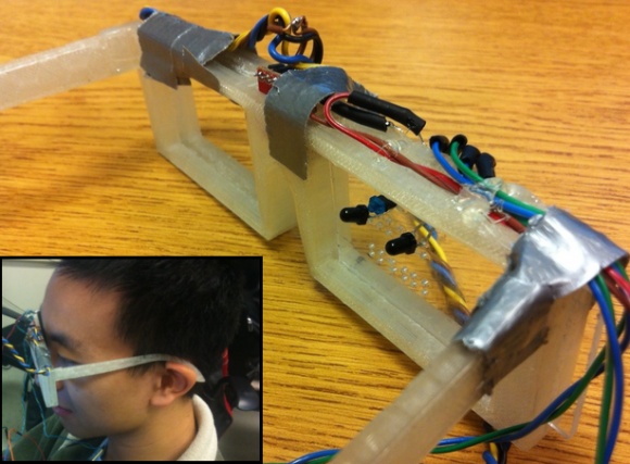
| 12:01 am | PhotoTransistor Based Eye-Tracking
The applications of eye-tracking devices are endless, which is why we always get excited to see new techniques in measuring the absolute position of the human eye. Cornell students [Michael and John] took on an interesting approach for their final project and designed a phototransistor based eye-tracking system. We can definitely see the potential of this project, but for their first prototype, the system relies on both eye-tracking and head movement to fully control a mouse pointer. An end-product design was in mind, so the system consists of both a pair of custom 3D printed glasses and a wireless receiver; thus avoiding the need to be tethered to the computer under control . The horizontal position of the mouse pointer is controlled via the infrared eye tracking mechanism, consisting of an Infrared LED positioned above the eye and two phototransistors located on each side of the eye. The measured analog data from the phototransistors determine the eye’s horizontal position. The vertical movement of the mouse pointer is controlled with the help of a 3-axis gyroscope mounted to the glasses. The effectiveness of a simple infrared LED/phototransistor to detect eye movement is impressive, because similar projects we’ve seen have been camera based. We understand how final project deadlines can be, so we hope [Michael and John] continue past the deadline with this one. It would be great to see if the absolute position (horizontal and vertical) of the eye can be tracked entirely with the phototransistor technique.
Filed under: Medical hacks  |
| Friday, January 3rd, 2014 | |
| 9:00 pm | Build an Audio Spectrum Analyzer the Analog Way
[Ryan] wanted a spectrum analyzer for his audio equipment. Rather than grab a micro, he did it the analog way. [Ryan] designed a 10 band audio spectrum analyzer. This means that he needs 10 band-pass filters. As the name implies, a band-pass filter will only allow signals with frequency of a selected band to pass. Signals with frequency above or below the filter’s passband will be attenuated. The band-pass itself is constructed from a high pass and a low pass filter. [Ryan] used simple resistor capacitor (RC) filters to implement his design. All those discrete components would quickly attenuate [Ryan's] input signal, so each stage uses two op-amps. The first stage is a buffer for each band. The second op-amp, located after the band-pass filters, is configured as a non-inverting amplifier. These amplifiers boost the individual band signals before they leave the board. [Ryan] even added an “energy filler” mode. In normal mode, the analyzer’s output will exactly follow the input signal. In “energy filler” (AKA peak detect) mode, the output will display the signal peaks, with a slow decay down to the input signal. The energy filler mode is created by using an n-channel FET to store charge in an electrolytic capacitor. Have we mentioned that for 10 bands, all this circuitry had to be built 10 times? Not to mention input buffering circuitry. With all this done, [Ryan] still has to build the output portion of the analyzer: 160 blue LEDs and their associated drive circuitry. Going “all analog” may seem crazy in this day and age of high-speed micro controllers and FFTs, but the simple fact is that these circuits work, and work well. The only thing to fear is perf board solder shorts. We think debugging those is half the fun. Filed under: classic hacks  |
| 6:00 pm | 3D Printering: Making A Thing In Blender, Part I
In case you weren’t aware, having a 3D printer is nothing like owning a real-life Star Trek replicator. For one, replicators are usually found on Federation starships and not hype trains. Secondly, the details of how replicated objects are designed in the 24th century is an issue completely left unexplored by TNG, and DS9, and only a minor plot point in a few Voyager episodes. Of the most likely possibilities, though, it appears replicated objects are either initially created by ‘scanning’ them with a teleporter, or commanding the ship’s computer to conjure something out of the hologrid. No, with your own 3D printer, if you want a unique object you actually have to design it yourself. Without a holodeck. Using your hands to move a mouse and keyboard. Savages. This series of ‘Making a Thing’ tutorials aims to fix that. With this post, we’re taking a look at Blender, an amazing 3D modeling and animation package. Because we still haven’t figured out the best way to combine multiple blog posts together as a single resource − we’re working on that, though − here’s the links to the previous “Making a Thing” posts: This list is sure to grow thanks to your suggestions on what 3D modeling software to feature, but for now let’s make a thing in Blender.
Our Thing
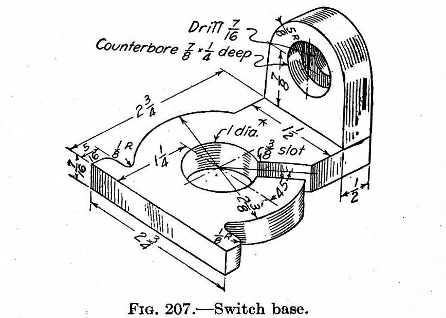
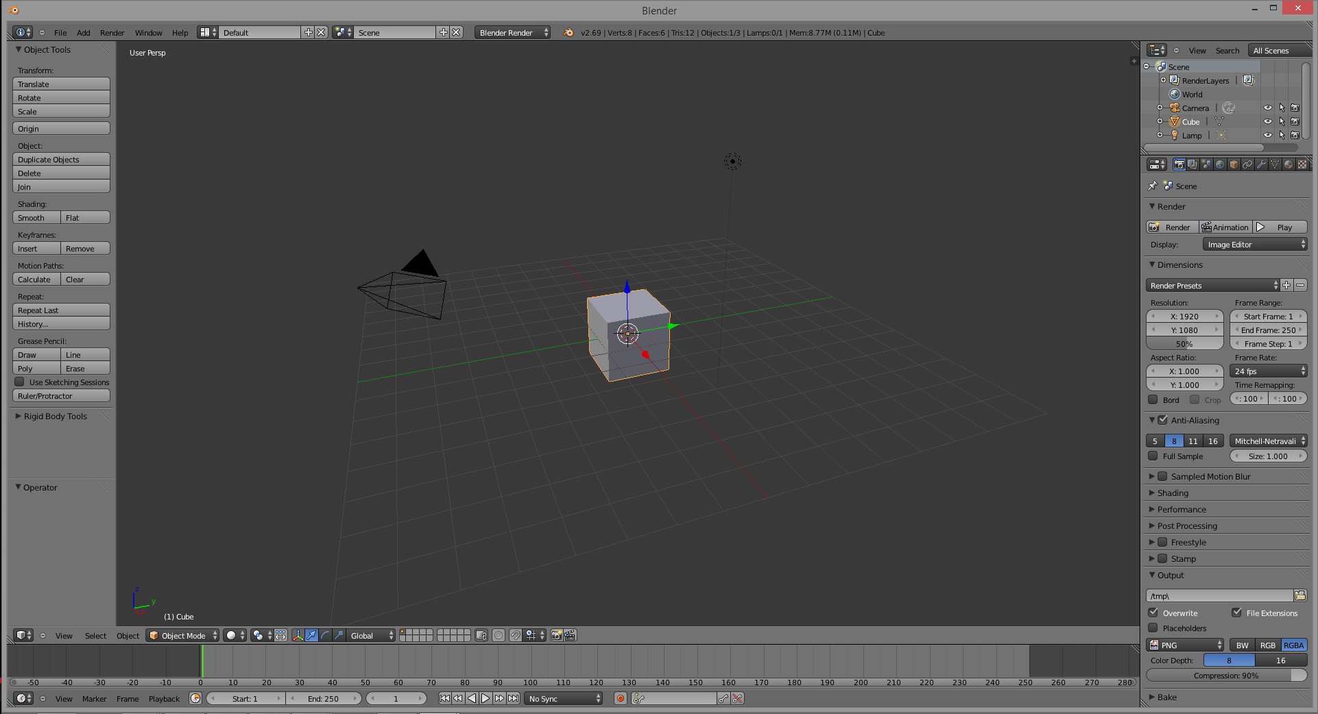
To the right is the part we’ll be designing in Blender. Just like the OpenSCAD and AutoCAD tutorials, we’re using the same object, a weird switch base thing taken from a 90-year-old book on drafting. You can click to embiggen that. A Word About BlenderBlender is designed as a 3D animation suite. You know the old mid-90s Pixar short films? You can make those with Blender easily. Using Blender to design a small object to send to a 3D printer is like using a bulldozer to build a sand castle. You can do it, but it’s overkill. Ideally, Blender should be used for objects that aren’t mechanical in nature. If you’re designing a gearbox for an RC car, don’t use Blender. If you’re making a replica of the Antikythera mechanism, don’t use Blender. If, however, you’re designing something more sculptural – a Pietà, for instance – Blender is a great tool. Despite Blender being complete overkill for this simple part, and the fact Blender isn’t well suited for designing mechanical parts anyway, a lot of people asked for a Blender tutorial. Who am I to argue with the commentors on Hackaday? Starting UpInstalling Blender is left as an exercise to the reader. Do that here. When you first start Blender you’ll see the following screen that includes a cube, a camera (the pyramid-looking thing), and lamp. This is the default starting screen and we don’t need any of these objects. On your right hand toolbar, go to your Scene tab (at the top of the toolbar), right-click the cube, camera, and lamp, and delete them.
MeshesNow that we have a blank canvas, we can start designing our part. Since this part of this tutorial is already halfway done, we’re only going to design the ‘washer’ part of our thing – the circle with a 3/8″ slot.
Instead of editing solids like OpenSCAD and AutoCAD, Blender does things entirely differently. It uses meshes, or collections of vertices (points in 3D space), edges (lines between two vertices), and faces (polygons made of edges) to define an object. We can start building our thing by making a cylinder mesh. From the top menu bar, select Add -> Mesh -> Cylinder and left click. A cylinder will appear at coordinates 0,0,0 in your scene.
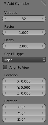
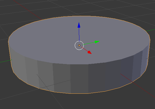
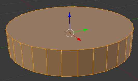
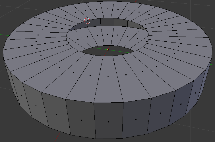
After you’ve done this, you’ll see an ‘Add Cylinder’ window on your left hand toolbar. This window allows you to edit the number of vertices, the radius, and the depth of the cylinder. Now is a good of a time as any to start editing our part, so make the radius of the cylinder 1.1875 (one half of the 2 3/8″ diameter of our part), and the depth 0.4375. By the way, yes, I am regretting using a part from a 100-year-old drafting textbook right about now. Here’s what we end up with:
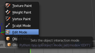
That’s making a very primitive object in Blender. To make anything useful, though, we need to go into edit mode.
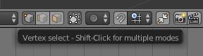
At the bottom of your Blender window, you’ll find a menu that will change how you can interact with Blender. Right now we’re in Object mode, which allows for the creation of meshes, surfaces, cameras, and lamps. To edit our object we need to be in…. Edit mode. Click on the little pull-down menu and change over. Doing this allows us to edit all the vertices, edges, and faces of our object. Here’s the cylinder we just created with all these selected:
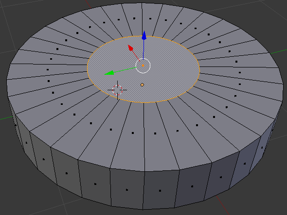
Hit the ‘A’ key on your keyboard to deselect everything. Now the cylinder is gray. Now we need to put a hole in this part of our thing. If we were modeling with solids, we would simply create another cylinder, smaller than the one we have now, and subtract it from our current model. We’re not working with solids, though; we need to create the faces of our objects without Boolean operations. To create the hole in this part of our thing, select the top face of the cylinder and with the ALT+F keyboard combo, select inset faces with the tool tip pop up thingy. Insetting a face allows us to create a new top and bottom for this cylinder that will correspond to the exact sized hole we need.
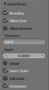
When you enable the Inset Faces command, the size of the hole you’re creating is dependant on how far you move your mouse; not great for something we’re creating from precise measurements. On the left hand toolbar, though, you can enter the thickness we want. Here’s how the math goes, if you’re wondering. The ‘cylinder’ of our part is 2 3/8″ in diameter, and we want a 1″ diameter hole in the middle. Subtract 1 inch from 2.375 and you get 1.375. Since the thickness of this face is in reality a radius, divide 1.375 by two and you’ll get the number we want. I truly hate decimal inches. After deleting the top part of our hole, flip the part over in Blender and do the same thing to the other circular face of our part. You’ll end up with something like this:
Now all we need to do is join up the top and bottom faces.
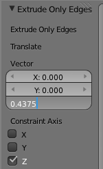
Instead of individually selecting each of these edges on the inside of our part and creating 36 individual faces, we’re going to do something much simpler. Holding down the ALT key, select one of the inside edges with the right mouse button. This enables edge loop selection. Now, on the mesh tools toolbar (left side), hit Extrude and press the ‘Z’ key on your keyboard to lock your mouse input to one axis of movement.
Again on the right toolbar, you’ll see a trio of boxes labeled ‘Vector’. This is how far Blender will extrude our…. extrusion in the X, Y, and Z axis. We want to extrude this edge 7/16″ (or 0.4375 decimal inches in the negative Z direction. That’s easy enough. Here’s what we end up with when that’s done. Yes, it took me one thousand words to describe how to create a washer in Blender. So what did you just learn?As far as the creation of our ‘thing’ in Blender, we didn’t get very far. There’s still flanges and holes and round overs to do, but this is only part one of this Blender tutorial. Hopefully this served as a good introduction to Blender’s meshes and editing those mesh’s faces and edges. See you here again next week! Filed under: 3d Printer hacks, Hackaday Columns, how-to  |
| 3:01 pm | 3D Acoustic Manipulation: Seeminly-Unreal Levitation Using Soundwaves
Wow. [Yoichi Ochiai], [Takayuki Hoshi] and [Jun Rekimoto] are researchers from the University of Tokyo and the Nagoya Institute of Technology, and they have just learned how to airbend. Using a series of standing ultrasound waves, it is possible to suspend small particles at the sound pressure nodes. The acoustic axis of the ultrasound beam is parallel to gravity, which also allows the objects to be manipulated along the fixed axis by varying the phase or frequencies of the sound. By adding a second ultrasound beam perpendicular to the first it is possible to localize the pressure node, or focal point, and levitate small objects around a 2D plane. In their demonstrations they float foam particles, a resistor, an LED, they show off the waves using a piece of dry ice, and even manage to float a small screw. Sound like crazy talk? Just watch the video.
Want to build your own? We covered a much more simple DIY Acoustic Levitator rig a few months ago. [via Hardware-360] Filed under: misc hacks  |
| 2:58 pm | Fire At The Geek Group
The Geek Group, an absurdly large and well stocked hackerspace in Grand Rapids, Michigan caught fire yesterday. You may recall The Geek Group from their many over-the-top projects that include a quarter shinker, a 200,000 Watt Tesla coil, enough capacitors to kill a demi-god, and a giant robot that crushes TVs. From what TGG has shown on their website and their YouTube, they have an amazing space that could still be the home of quite a few amazing builds. According to Geek Group head honcho [Chris], the fire was caused by an overheated electric motor. No one was at the space at the time, but the fire was hot enough to crack the exterior brick and melt porcelain insulators in their high voltage lab. To add insult to injury, this was only TGG’s second day of being open to the public. The folks at The Geek Group are looking for volunteers for their cleanup, so if you’re around the Grand Rapids area and would like to pitch in, head on over around noon today. Filed under: Hackerspaces, news  |
| 12:01 pm | A Low Cost Dual Discriminator Module for the Easy-phi Project
A few months ago I presented you the Easy-phi project, which aims at building a simple, cheap but intelligent rack-based open hardware/software platform for hobbyists. With easy-phi, you simply have a rack to which you add cards (like the one shown above) that perform the functions you want. Recently my team finished testing our FPGA-based discriminator or “universal input” if you prefer. As easy-phi cards use a well-defined electrical signal to communicate with each other, we needed to make a card that would translate the different kinds of electrical signals from the outside, as well as perform plenty of other functions. It was therefore designed to have a 100MHz input bandwidth with an AC/DC coupled 50 ohm/high impedance input stage (x2) and 4 easy-phi outputs. For this module, we picked the (old) spartan3-an FPGA to perform the different logic functions that may be needed by the final users (high speed counter, OR/XOR/AND, pulse creation,…). Using the cortex-m3 microcontroller present on the board, it may be easily reconfigured at will. All design resources may be found on our Github, and you can always have a look at our official website. Filed under: Arduino Hacks, ARM, hardware  |
| 9:00 am | Myst(ery) Box
Anyone remember the game Myst? Well, [Michael] and his girlfriend have been playing quite a bit of it lately, so for her birthday, he decided to make her something inspired from it. For those unaware of the classic that is the Myst series, it is a set of games that started back in 1993 where you assume the role of the Stranger who gets to explore other planets (called Ages) to solve various logical and mechanical puzzles. Anyway, [Michael] got his girlfriend tickets to visit GC319QK (a geocache site requiring diving) — since the gift is a relatively small token, it was logical for [Michael] to make a fancy box for it — and that’s exactly what he did. It’s a peculiar little wooden box with LEDs, a button, a latch, an unplugged wire, different rods and strange looking sensors — and it is a very clever little puzzle. We could explain to you how it works (with the Arduino, phototransistors and maybe the source code), but instead we think you’ll enjoy watching [Michael's] video of it.
Now since the present is for geocaching, we’re almost surprised he didn’t include a reverse geocache puzzle in it too! [Via Reddit] Filed under: Arduino Hacks  |