[Most Recent Entries] [Calendar View] [Friends View]
Friday, January 3rd, 2014
| Time | Event |
| 12:00a | Un-crapifying a Car Stereo
[Noah Farrington] has just accomplished a major milestone in his life, purchasing his first car! A glorious 2001 Ford Focus wagon. While it may be a fully loaded luxury vehicle, it is missing one thing poor [Noah] can’t live without. An aux-in port. He had a few options for rectifying the situation. Live with it as is, hack the strange Ford media protocol out of the back, or fool the CD player into playing his input. Naturally he chose the third option. His first challenge was removing the deck from the car. People told him he’d have to buy fancy stereo removal tools — he made do with tent pegs and coat hangers. Using the same method as described in a past aux-in hack, he identified the audio in leads on the CD player’s ribbon cable. By carefully soldering in his own aux-in plug, he’s almost ready for business! Unfortunately, the CD player also needs to think that it is on for it to properly output the audio. [Noah] chose the simple solution — record a silent CD to always leave in the deck. Stick around after the break to see it in action.
He might not be driving a classic 1974 Pacer, but at least now he can rock out to the digitally remastered Bohemian Rhapsody off of his phone! Filed under: digital audio hacks |
| 3:00a | Gesture Based Security Lock
A team of students from Cornell University are looking into alternative ways of creating a security system that can be locked or unlocked by using physical gestures in an enclosed space. It is the final year project for [Ankur], [Darshan] and [Saisrinivasan] in their MEng of Electrical and Computer Engineering. The system prototype is capable of recording a gesture and then comparing the gesture with future gestures to lock or unlock the system. Consider it like a secret handshake to get into the office! To analyze the gesture they are using four SparkFun proximity sensors setup in a linear array to sense the distance a hand is moved. An ATMega1284P is used to convert the analog sensor signal to digital for further processing. The project is extremely well documented, as it appears to be the final report for the project. A short video after the break shows off the prototype and gives a good explanation of how the system works.
Filed under: security hacks |
| 6:00a | Spoofing Pokemon Trades [Adan] had an old Game Boy sitting around, and without anything better to do decided to investigate the link cable protocol with a microcontroller. He had a Stellaris Launchpad for the task, but initially had no project in mind. What he came up for this adventure in serial protocols is a first gen Pokemon trade spoofer that allows him to obtain pokemon without having two Game Boys, or for the weird ones out there, “friends.” The Game Boy link protocol is extremely well documented, so getting data from the Game Boy to the Launchpad was as simple as a soldering up an old link cable connector to a piece of perf board. After figuring out the electronics, [Adan] looked at what happened when two Pokemon games tried to trade pokemon. When two Game Boys are linked, there are two in-game options: trade or battle. Looking at the data coming after the ‘trade’ option, [Adan] found something that could possibly be the data structure of the Pokemon being sent. He reverse-engineered this all by himself before discovering this is also well documented. Bringing everything together, [Adan] figured out how to trade non-existent Pokemon with a small dev board. Right now he’s only transmitting Pokemon that are hard-coded on the Launchpad, but it’s very possible to transmit the Pokemon values in real-time over USB. Thanks [Dan] for sending this in, and no, we don’t know what’s up with the influx of Pokemon posts over the last week. Video of the spoof below.
Filed under: nintendo gameboy hacks |
| 9:00a | Myst(ery) Box
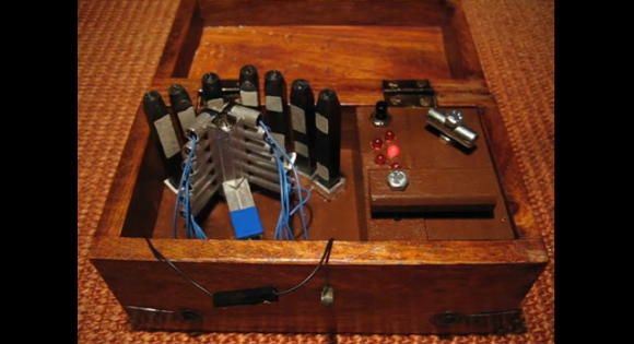
Anyone remember the game Myst? Well, [Michael] and his girlfriend have been playing quite a bit of it lately, so for her birthday, he decided to make her something inspired from it. For those unaware of the classic that is the Myst series, it is a set of games that started back in 1993 where you assume the role of the Stranger who gets to explore other planets (called Ages) to solve various logical and mechanical puzzles. Anyway, [Michael] got his girlfriend tickets to visit GC319QK (a geocache site requiring diving) — since the gift is a relatively small token, it was logical for [Michael] to make a fancy box for it — and that’s exactly what he did. It’s a peculiar little wooden box with LEDs, a button, a latch, an unplugged wire, different rods and strange looking sensors — and it is a very clever little puzzle. We could explain to you how it works (with the Arduino, phototransistors and maybe the source code), but instead we think you’ll enjoy watching [Michael's] video of it.
Now since the present is for geocaching, we’re almost surprised he didn’t include a reverse geocache puzzle in it too! [Via Reddit] Filed under: Arduino Hacks |
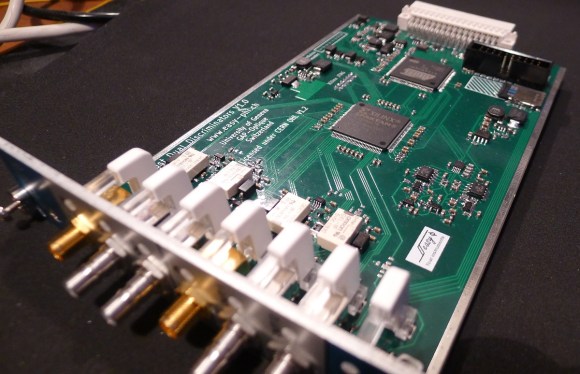
| 12:01p | A Low Cost Dual Discriminator Module for the Easy-phi Project A few months ago I presented you the Easy-phi project, which aims at building a simple, cheap but intelligent rack-based open hardware/software platform for hobbyists. With easy-phi, you simply have a rack to which you add cards (like the one shown above) that perform the functions you want. Recently my team finished testing our FPGA-based discriminator or “universal input” if you prefer. As easy-phi cards use a well-defined electrical signal to communicate with each other, we needed to make a card that would translate the different kinds of electrical signals from the outside, as well as perform plenty of other functions. It was therefore designed to have a 100MHz input bandwidth with an AC/DC coupled 50 ohm/high impedance input stage (x2) and 4 easy-phi outputs. For this module, we picked the (old) spartan3-an FPGA to perform the different logic functions that may be needed by the final users (high speed counter, OR/XOR/AND, pulse creation,…). Using the cortex-m3 microcontroller present on the board, it may be easily reconfigured at will. All design resources may be found on our Github, and you can always have a look at our official website. Filed under: Arduino Hacks, ARM, hardware |
| 2:58p | Fire At The Geek Group The Geek Group, an absurdly large and well stocked hackerspace in Grand Rapids, Michigan caught fire yesterday. You may recall The Geek Group from their many over-the-top projects that include a quarter shinker, a 200,000 Watt Tesla coil, enough capacitors to kill a demi-god, and a giant robot that crushes TVs. From what TGG has shown on their website and their YouTube, they have an amazing space that could still be the home of quite a few amazing builds. According to Geek Group head honcho [Chris], the fire was caused by an overheated electric motor. No one was at the space at the time, but the fire was hot enough to crack the exterior brick and melt porcelain insulators in their high voltage lab. To add insult to injury, this was only TGG’s second day of being open to the public. The folks at The Geek Group are looking for volunteers for their cleanup, so if you’re around the Grand Rapids area and would like to pitch in, head on over around noon today. Filed under: Hackerspaces, news |
| 3:01p | 3D Acoustic Manipulation: Seeminly-Unreal Levitation Using Soundwaves
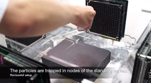
Wow. [Yoichi Ochiai], [Takayuki Hoshi] and [Jun Rekimoto] are researchers from the University of Tokyo and the Nagoya Institute of Technology, and they have just learned how to airbend. Using a series of standing ultrasound waves, it is possible to suspend small particles at the sound pressure nodes. The acoustic axis of the ultrasound beam is parallel to gravity, which also allows the objects to be manipulated along the fixed axis by varying the phase or frequencies of the sound. By adding a second ultrasound beam perpendicular to the first it is possible to localize the pressure node, or focal point, and levitate small objects around a 2D plane. In their demonstrations they float foam particles, a resistor, an LED, they show off the waves using a piece of dry ice, and even manage to float a small screw. Sound like crazy talk? Just watch the video.
Want to build your own? We covered a much more simple DIY Acoustic Levitator rig a few months ago. [via Hardware-360] Filed under: misc hacks |
| 6:00p | 3D Printering: Making A Thing In Blender, Part I
In case you weren’t aware, having a 3D printer is nothing like owning a real-life Star Trek replicator. For one, replicators are usually found on Federation starships and not hype trains. Secondly, the details of how replicated objects are designed in the 24th century is an issue completely left unexplored by TNG, and DS9, and only a minor plot point in a few Voyager episodes. Of the most likely possibilities, though, it appears replicated objects are either initially created by ‘scanning’ them with a teleporter, or commanding the ship’s computer to conjure something out of the hologrid. No, with your own 3D printer, if you want a unique object you actually have to design it yourself. Without a holodeck. Using your hands to move a mouse and keyboard. Savages. This series of ‘Making a Thing’ tutorials aims to fix that. With this post, we’re taking a look at Blender, an amazing 3D modeling and animation package. Because we still haven’t figured out the best way to combine multiple blog posts together as a single resource − we’re working on that, though − here’s the links to the previous “Making a Thing” posts: This list is sure to grow thanks to your suggestions on what 3D modeling software to feature, but for now let’s make a thing in Blender.
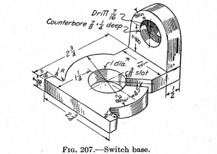
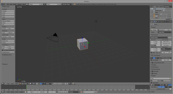
Our ThingTo the right is the part we’ll be designing in Blender. Just like the OpenSCAD and AutoCAD tutorials, we’re using the same object, a weird switch base thing taken from a 90-year-old book on drafting. You can click to embiggen that. A Word About BlenderBlender is designed as a 3D animation suite. You know the old mid-90s Pixar short films? You can make those with Blender easily. Using Blender to design a small object to send to a 3D printer is like using a bulldozer to build a sand castle. You can do it, but it’s overkill. Ideally, Blender should be used for objects that aren’t mechanical in nature. If you’re designing a gearbox for an RC car, don’t use Blender. If you’re making a replica of the Antikythera mechanism, don’t use Blender. If, however, you’re designing something more sculptural – a Pietà, for instance – Blender is a great tool. Despite Blender being complete overkill for this simple part, and the fact Blender isn’t well suited for designing mechanical parts anyway, a lot of people asked for a Blender tutorial. Who am I to argue with the commentors on Hackaday? Starting UpInstalling Blender is left as an exercise to the reader. Do that here. When you first start Blender you’ll see the following screen that includes a cube, a camera (the pyramid-looking thing), and lamp. This is the default starting screen and we don’t need any of these objects. On your right hand toolbar, go to your Scene tab (at the top of the toolbar), right-click the cube, camera, and lamp, and delete them. MeshesNow that we have a blank canvas, we can start designing our part. Since this part of this tutorial is already halfway done, we’re only going to design the ‘washer’ part of our thing – the circle with a 3/8″ slot.
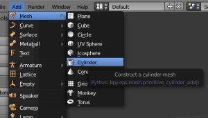
Instead of editing solids like OpenSCAD and AutoCAD, Blender does things entirely differently. It uses meshes, or collections of vertices (points in 3D space), edges (lines between two vertices), and faces (polygons made of edges) to define an object. We can start building our thing by making a cylinder mesh. From the top menu bar, select Add -> Mesh -> Cylinder and left click. A cylinder will appear at coordinates 0,0,0 in your scene.
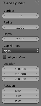
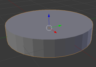
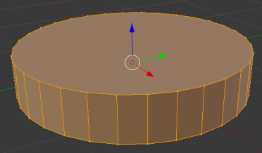
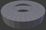
After you’ve done this, you’ll see an ‘Add Cylinder’ window on your left hand toolbar. This window allows you to edit the number of vertices, the radius, and the depth of the cylinder. Now is a good of a time as any to start editing our part, so make the radius of the cylinder 1.1875 (one half of the 2 3/8″ diameter of our part), and the depth 0.4375. By the way, yes, I am regretting using a part from a 100-year-old drafting textbook right about now. Here’s what we end up with: That’s making a very primitive object in Blender. To make anything useful, though, we need to go into edit mode.
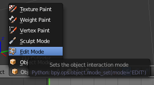
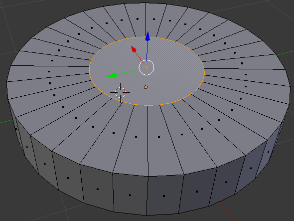
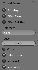
At the bottom of your Blender window, you’ll find a menu that will change how you can interact with Blender. Right now we’re in Object mode, which allows for the creation of meshes, surfaces, cameras, and lamps. To edit our object we need to be in…. Edit mode. Click on the little pull-down menu and change over. Doing this allows us to edit all the vertices, edges, and faces of our object. Here’s the cylinder we just created with all these selected: Hit the ‘A’ key on your keyboard to deselect everything. Now the cylinder is gray. Now we need to put a hole in this part of our thing. If we were modeling with solids, we would simply create another cylinder, smaller than the one we have now, and subtract it from our current model. We’re not working with solids, though; we need to create the faces of our objects without Boolean operations. To create the hole in this part of our thing, select the top face of the cylinder and with the ALT+F keyboard combo, select inset faces with the tool tip pop up thingy. Insetting a face allows us to create a new top and bottom for this cylinder that will correspond to the exact sized hole we need. When you enable the Inset Faces command, the size of the hole you’re creating is dependant on how far you move your mouse; not great for something we’re creating from precise measurements. On the left hand toolbar, though, you can enter the thickness we want. Here’s how the math goes, if you’re wondering. The ‘cylinder’ of our part is 2 3/8″ in diameter, and we want a 1″ diameter hole in the middle. Subtract 1 inch from 2.375 and you get 1.375. Since the thickness of this face is in reality a radius, divide 1.375 by two and you’ll get the number we want. I truly hate decimal inches. After deleting the top part of our hole, flip the part over in Blender and do the same thing to the other circular face of our part. You’ll end up with something like this: Now all we need to do is join up the top and bottom faces.
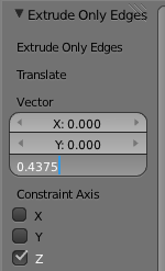
Instead of individually selecting each of these edges on the inside of our part and creating 36 individual faces, we’re going to do something much simpler. Holding down the ALT key, select one of the inside edges with the right mouse button. This enables edge loop selection. Now, on the mesh tools toolbar (left side), hit Extrude and press the ‘Z’ key on your keyboard to lock your mouse input to one axis of movement. Again on the right toolbar, you’ll see a trio of boxes labeled ‘Vector’. This is how far Blender will extrude our…. extrusion in the X, Y, and Z axis. We want to extrude this edge 7/16″ (or 0.4375 decimal inches in the negative Z direction. That’s easy enough. Here’s what we end up with when that’s done. Yes, it took me one thousand words to describe how to create a washer in Blender. So what did you just learn?As far as the creation of our ‘thing’ in Blender, we didn’t get very far. There’s still flanges and holes and round overs to do, but this is only part one of this Blender tutorial. Hopefully this served as a good introduction to Blender’s meshes and editing those mesh’s faces and edges. See you here again next week! Filed under: 3d Printer hacks, Hackaday Columns, how-to |
| 9:00p | Build an Audio Spectrum Analyzer the Analog Way
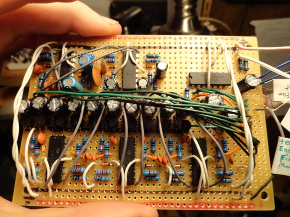
[Ryan] wanted a spectrum analyzer for his audio equipment. Rather than grab a micro, he did it the analog way. [Ryan] designed a 10 band audio spectrum analyzer. This means that he needs 10 band-pass filters. As the name implies, a band-pass filter will only allow signals with frequency of a selected band to pass. Signals with frequency above or below the filter’s passband will be attenuated. The band-pass itself is constructed from a high pass and a low pass filter. [Ryan] used simple resistor capacitor (RC) filters to implement his design. All those discrete components would quickly attenuate [Ryan's] input signal, so each stage uses two op-amps. The first stage is a buffer for each band. The second op-amp, located after the band-pass filters, is configured as a non-inverting amplifier. These amplifiers boost the individual band signals before they leave the board. [Ryan] even added an “energy filler” mode. In normal mode, the analyzer’s output will exactly follow the input signal. In “energy filler” (AKA peak detect) mode, the output will display the signal peaks, with a slow decay down to the input signal. The energy filler mode is created by using an n-channel FET to store charge in an electrolytic capacitor. Have we mentioned that for 10 bands, all this circuitry had to be built 10 times? Not to mention input buffering circuitry. With all this done, [Ryan] still has to build the output portion of the analyzer: 160 blue LEDs and their associated drive circuitry. Going “all analog” may seem crazy in this day and age of high-speed micro controllers and FFTs, but the simple fact is that these circuits work, and work well. The only thing to fear is perf board solder shorts. We think debugging those is half the fun. Filed under: classic hacks |
| << Previous Day |
2014/01/03 [Calendar] |
Next Day >> |


